LED asynchronous control cards are thecore hubfor debugging irregular-shaped LED screens—whether it’s a mall letter display, traffic guidance screen, cross-shaped sign, or curved panel, nearly all non-standard LED setups rely on them for stable performance. But as irregular-shaped screens become more common, traditional debugging methods are hitting walls: image tearing, driver incompatibility, communication failures… These issues can mean hours of rework or even project delays. 今日, I’m sharing 10 years of LED engineering experience to break down thecore techof asynchronous control cards: data group offset. Follow this guide, and you’ll avoid 90% of debugging pitfalls.
私. Asynchronous Control Cards: From Offline Playback to Irregular-Screen Hub
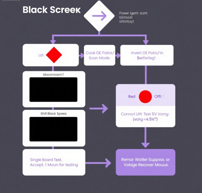
LED Display Black Screen Troubleshooting Flowchart – Diagnosing Power, Signal Polarity, and Voltage Issues
Asynchronous control cards (aka “offline cards”) are theindependent processing brainof LED displays. They store content locally to play without a computer—perfect for fixed setups like storefront signs or traffic screens. Their biggest perks?
Offline stability: Keeps playing even if power drops; update content via USB, serial port, or 4G.
Smart maintenance: Schedules power-on/off, monitors temp/humidity, cuts down on manual checks.
Anti-interference: No real-time computer connection means fewer signal glitches.
But here’s the problem: Irregular-shaped screens (crosses, letters, 曲線) are breaking traditional debugging. Two big pain points:
Image tearing: Rectangular modules pieced into odd shapes cause signal misalignment—text breaks, images shift.
Driver mismatch: If your control card doesn’t match the module’s scan mode (1/4, 1/8, 1/16 スキャン) or interface (HUB75B, 08), you get black screens or static.
Case Warning: A mall’s “OPEN” letter screen had no data group offset—ended up showing “O·P·E·N” with gaps. Rework took 8 時間, and the client almost withheld payment.
Ⅱ. データグループオフセット: The #1 Tool for Irregular-Screen Debugging
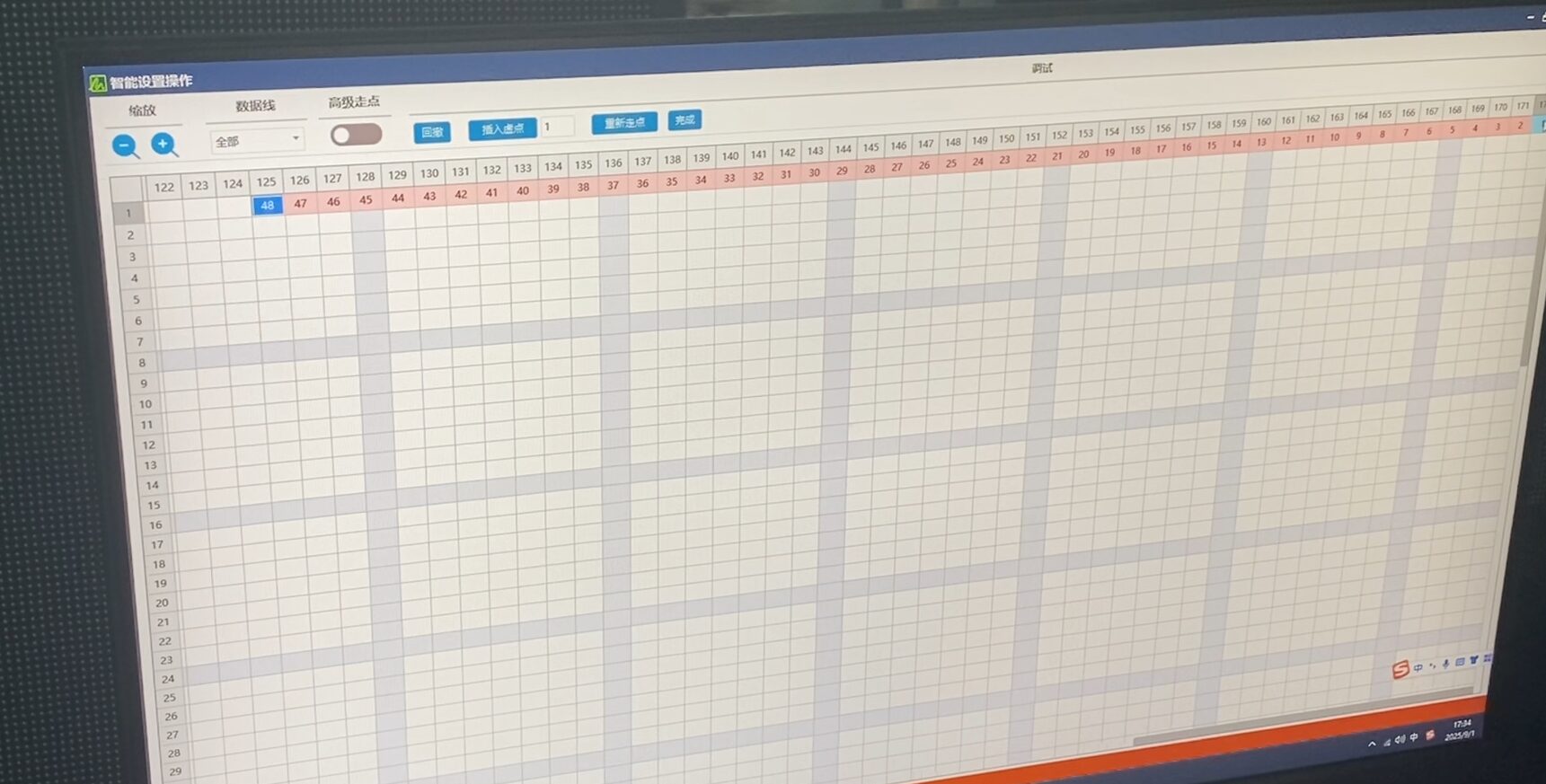
LED Display Test Card Software Interface – Technician Adjusting Parameters for Screen Calibration and Debugging
1. When Do You Need Data Group Offset?
If your receiver card is drivingnon-rectangular module setups (crosses, stairs, letters), youmustuse data group offset. Why? Because rectangular modules don’t fit odd shapes—signal paths get wonky, and your screen looks broken.
2. Key Terms to Master First
Before you touch any settings, memorize these 3 terms (they’re make-or-break):
Term
Definition
例
Data Group
A set of color signals (full-color = R+G+B).
1 data group = 3 color channels (R/G/B).
Interface Data Group
Signals defined by the module’s interface (例えば, HUB75B has 2 groups).
HUB75B = 2 RGB groups (6 signals total).
Offset Value
How much you shift a data group to fix misalignment.
32-pixel misalignment → 32-point offset.
3. Step-by-Step: Fix a Cross-Screen with P6 Modules
Problem: A cross-screen’s upper/lower modules are misaligned by 32 pixels—text splits into two. 解決 (using HDPlayer software):
Open HDPlayer → Go to “Hardware Settings” → Find “Data Group Offset”.
Select Data Groups 1, 2, 7, 8 (these control the cross’s top/bottom). Offset each by 32 ポイント.
Set resolution to the screen’s max size (例えば, cross top width + middle height = 640×320).
Before & After:
Before: “O·P” (broken text).
After: “OPEN” (perfectly aligned—even the “E” is whole!).
チップ用: Offset value = how many pixels your modules are misaligned. For P6 modules (32×16 pixels), 1 module off = 32-point offset.
Ⅲ. Top Debugging Pitfalls & How to Fix Them
1. 黒い画面? Follow This 4-Step Rescue
Black screens are scary, but 90% of them are fixable with this flow:
Check the power light:
Red light on? Problem is OE polarity/scan mode.
Red light off? Disconnect all modules—test the control card’s 5V voltage.
Fix OE polarity: If the light’s on, flip the OE polarity in software (例えば, “reverse” instead of “forward”).
Voltage check: If voltage is <4.5v, replace the power supply or add a regulator.
Single-board test: Still black? Connectonly one module—indoor 16-scan modules will burn the 4953 chip if you power the whole screen at once!
2. Communication Failure? Avoid These 3 Traps
Transferring content and getting errors? Here’s what’s wrong (and how to fix it):
Fault Symptom
Root Cause
Fix It Fast
“Error occurred” prompt
Serial baud rate mismatch
Sync control card jumpers with software (例えば, 38400).
USB read timeout
No independent power
Give the control card its own 5V power—add a ferrite ring for anti-interference.
485 network lockup
Parallel cables
Use star topology + 120Ω termination resistor.
3. Screen Distortion/Bright Lines? Use This Chart
For weird lines or static, skip the guesswork—use this table:
症状
Hardware Issue
Software Fix
Horizontal bright lines
Reversed ribbon cable
Flip the module’s ribbon cable.
Missing color blocks
Wrong data group definition
Reset RGB grouping (例えば, HUB75B = 2 groups).
Uneven row brightness
Inverted OE polarity
Check “Invert OE” in software.
Ⅳ. 10-Year Engineer’s Rules: Save Time & Money
1. Power Rule #1: Never Steal Power from Modules
Control cardsmusthave their own 5V power supply (±0.25V tolerance). Stealing power from modules causes voltage spikes—your control card’s program will crash, leading to screen distortion or burned chips.
Outdoor Tip: Add a surge protector. Ground it ≥10cm from the screen frame—static will kill your control card otherwise.
2. Environment Rule: Temp & Humidity Are Enemies
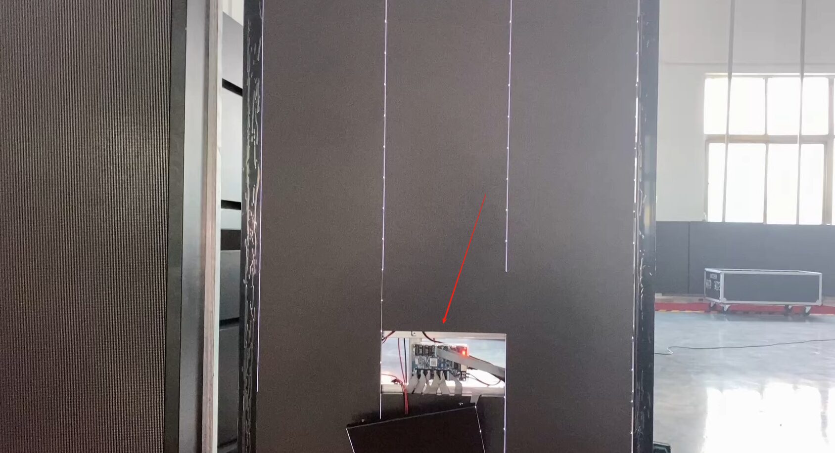
LED Display Module Quality Control Testing – Internal Circuitry and Component Inspection During Manufacturing Process
温度: Use industrial-grade control cards (-30°C to 70°C). Consumer-grade (-0℃~50℃) will freeze in northern winters.
Humidity: Put silica gel in the control card box. Humidity >60% RH corrodes circuit boards—southern spring rains are brutal for this.
3. Wireless Update Rules: Don’t Skip These Details
4G Control Cards: Fill SIM slots with conductive foam. Dust oxidizes the slot—many sites lose signal after a month.
WiFi Control Cards: Keep the antenna ≥20cm from power cables. EM interference weakens signals by 30%—you’ll get constant timeouts.
結論: The Future of Asynchronous Control Cards
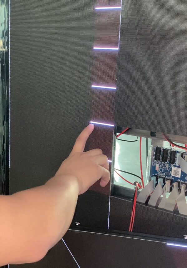
LEDディスプレイモジュール
Asynchronous control cards aren’t just “playback tools” anymore—they’resignal commandersfor creative screens. Data group offset lets you turn rectangular modules into any shape. Dual-channel communication (USB + 4G) makes updates stable, even for remote traffic screens.
Real-World Win: An airport’s curved navigation screen used to take 3 days to debug. With data group offset? 1 day. The client said: “You’re the only team that gets irregular screens.”
What’s Next?Future control cards will focus on:
Distributed Storage: LZW compression triples storage—no more swapping USB drives.
Arrayed Control: Multiple control cards work together—saves 21.9% energy for big screens (like stadium rings).