Building a high-quality LED display that’s stable, bright, and visually stunning isn’t just about stacking modules—it’s about nailing every detail from client conversations to final power-up. I’ve spent 8 years installing LEDs, and I’ve seen it all: rework from bad measurements, burnt boards from wrong wiring, and clients disappointed by blurry screens. Today, I’m breaking down the exact step-by-step process to build an LED display—plus the critical mistakes to avoid so you save time, money, and headaches.
I. Preliminary Communication: Lock Down Requirements (Or Regret It Later)
The first step in LED display building isn’t buying materials—it’s talking to your client. Get these 3 things right, and you’ll skip 80% of future problems:
1. Confirm Installation Location & Type
Mounting Style: Is it recessed (built into a wall), wall-mounted, or freestanding? For recessed screens, remind the client to reserve carpentry space 10mm larger than the screen (e.g., a 3940×2020mm screen needs 3950×2030mm). If not, you’ll be hacking into walls to make it fit—trust me, it’s not fun.
Environment: Indoor or outdoor? Outdoor screens need a waterproof back panel (aluminum composite or OSB board). Indoor recessed screens don’t, but they must have 300mm of depth for heat dissipation.
2. Nail Down Screen Specs
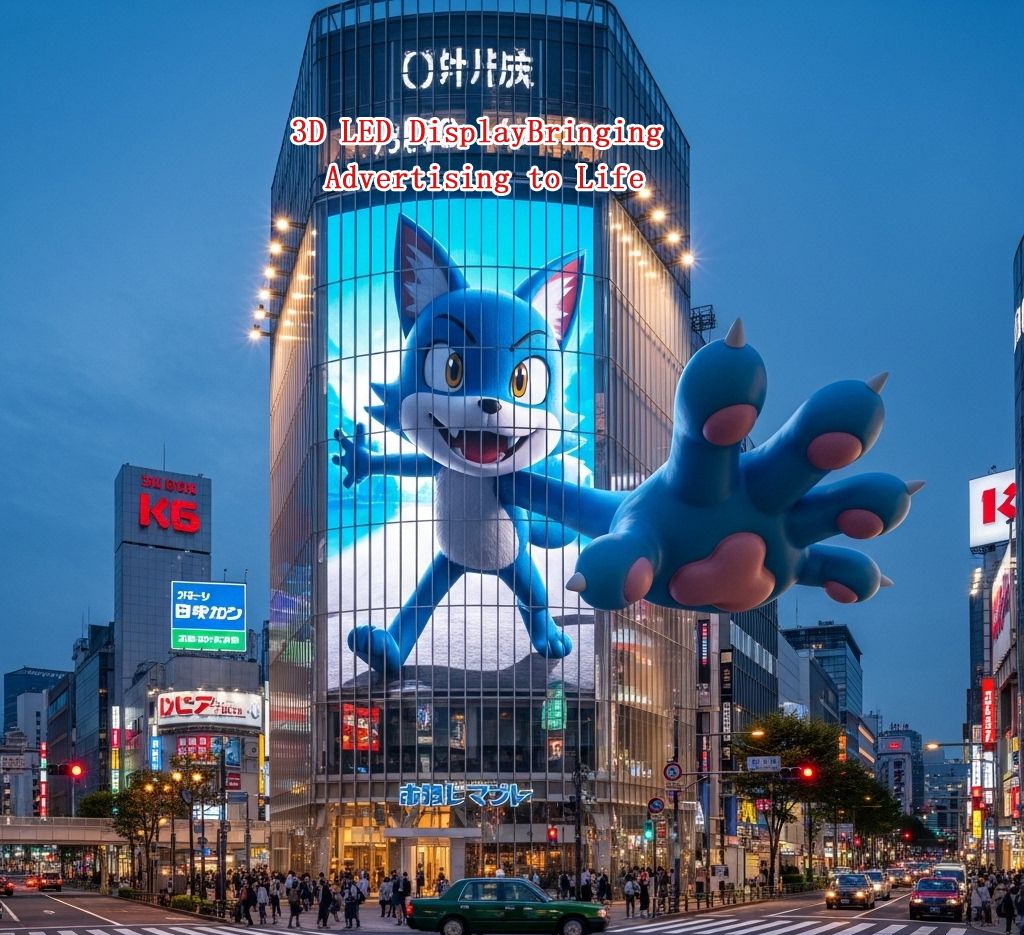
3D LED Advertising Display – Dynamic Ad Effect Featuring a Blue Cartoon Fox Leaping from Building Facade – Outdoor Digital Signage Case Study in Urban Commercial District
Pixel Pitch: This is non-negotiable. Indoor screens use P2/P3 (smaller = sharper). Outdoor screens need P10/P16 (bigger pixels = less glare).
Dimensions: Calculate screen size using module dimensions. For example, a P2 module (320×160mm) needs 12 modules for a 3.94m-wide screen (12×320mm=3840mm—add 10mm for frame tolerance). Pro tip: Always confirm the visible display area with the client—not the outer frame. Most clients mix these up!
3. Agree on Aesthetics
If the client wants black brushed titanium edging, clarify: Edging clips onto the frame and must be installed after the screen is assembled. Install it too early, and you won’t fit the modules.
II. Materials & Tools: List Everything (No Last-Minute Runs)
LED display building requires 4 core material categories—and tools that can cut, drill, and strip wire. Skip something, and you’ll be stuck mid-project:
1. Material List (Indoor P2 Embedded Screen Example)
Category
Materials & Specs
Notes
Frame
Aluminum extrusions (e.g., 9035 profile), corner connectors, magnetic rails
Magnetic rails let you attach modules without screws—game-changer!
Display Panel
Xvisuallive P2 Full-Color E Series Modules (320×160mm), 16P ribbon cables
Use high-refresh modules—no motion blur = happy clients.
Control System
Asynchronous control card (Nova/Calette), adapter board, Cat5e network cable
1 network cable supports 650,000 pixels—2M pixels need 3 cables.
III. Frame Assembly: Precision Is King—1mm Off = Big Problems
The frame is your screen’s skeleton. If it’s crooked, the modules will be too. Use a weld-free E-structure (CNC-machined for precision)—it’s easy to assemble and super accurate.
1. Cut & Assemble the Frame
Measure twice, cut once: Cut aluminum profiles to match the screen’s net size (subtract 4mm for tolerance—5mm if over 3m).
Secure corners: Use self-tapping screws to attach corners to profiles. Tighten firmly—loose corners = wobbly frame.
2. Install Magnetic Rails
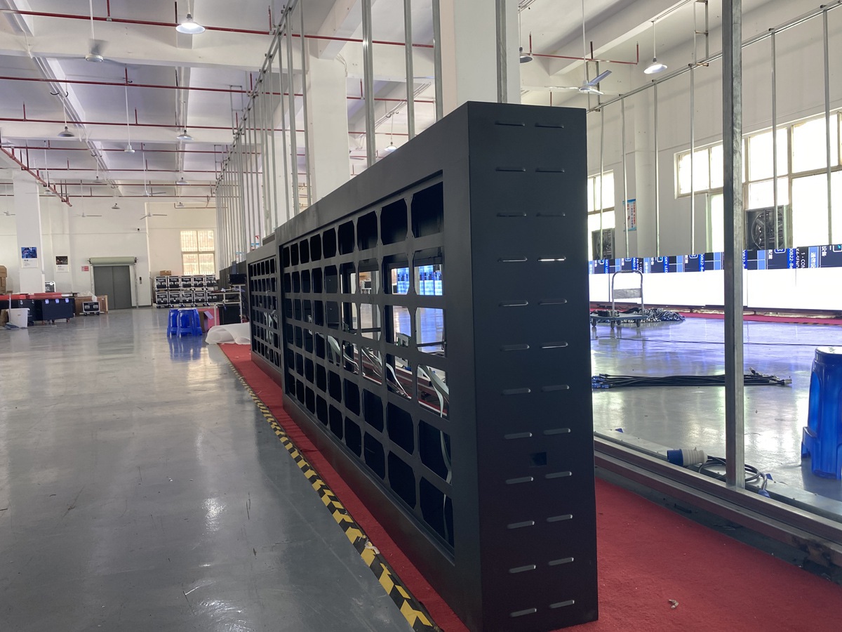
Large LED display cabinet in a spacious factory workshop, showcasing the manufacturing process of outdoor LED screens.
Align magnetic rails with module height (e.g., 160mm for P2 modules). Make sure rails are level—use a spirit level! Unlevel rails = uneven modules.
IV. Module Assembly: Slow & Steady—Rushing = Mistakes
Putting modules together is a skill. RUSH, and you’ll get 磕灯 (broken LEDs), gaps, or uneven screens.
1. Lay Out Modules Correctly
Follow the arrow: Modules have a direction arrow—point it right/down (consistent for all). Wrong direction = inverted images.
Check flatness: Use a spirit level on every module. Height difference ≤1mm—any more, and the screen will look “bumpy.”
2. Secure Modules & Fix Gaps
Magnet placement: Attach magnets to module corners (not just the center). This keeps modules flat and stable.
Gap consistency: Keep module gaps ≤0.5mm. Big gaps = broken text during playback.
3. Critical Pitfalls to Avoid
Don’t knock the LEDs! P2 LEDs are extremely small—just one bump can cause a dark spot.
Always support the module from the back, never touch the front.
V. Wiring: Do This Right—Or Burn Your Boards
Wiring is the #1 place people mess up. Reverse polarity or use series wiring, and you’ll fry your control card or modules.
1. Power Cable Rules (Don’t Reverse Polarity!)
VCC/+5V = positive: GND/COM = negative. Double-check—this is non-negotiable.
Parallel, not series: Power modules in parallel (positive to positive, negative to negative). Series wiring = voltage drops = burnt boards.
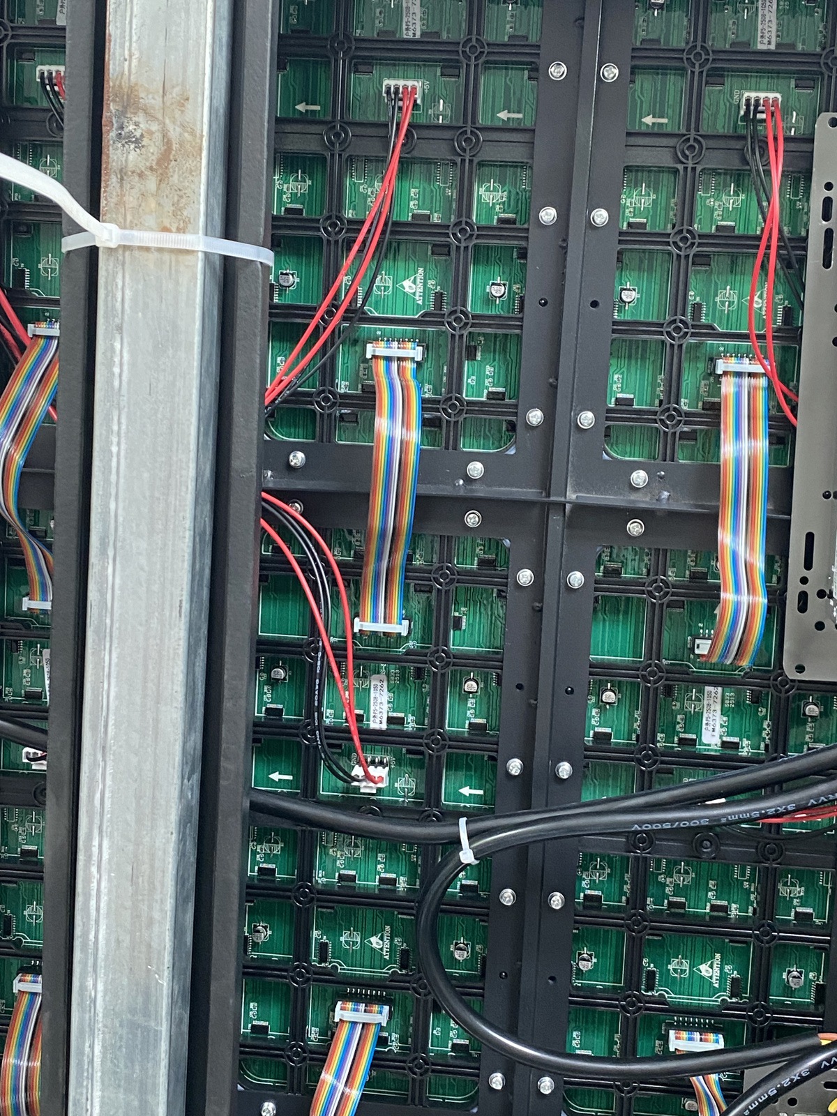
2. Ribbon Cables & Control Card Setup
Ribbon cable direction: Red edge faces left. Wrong direction = misaligned images.
Control card power: Use a dedicated 5V line from the power supply—no module power! Unstable voltage = frozen screens.
Network cable limits: Don’t overload. 650k pixels per cable—add more if needed.
VI. Cleaning: Small Debris = Big Troubles
Don’t skip this! Aluminum filings, wire bits, or dust inside the screen = short circuits.
Wipe the frame with a dust cloth.
Blow module gaps with a hairdryer—get rid of every piece of debris.
VII. Power-Up Testing: Follow the Sequence—Don’t Guess
Finally—time to turn it on! Remember: Power supply first, then control card. Reverse it, and you’ll burn the control card.
1. Connect & Configure the Control Card
WiFi setup: Connect your phone to the control card’s WiFi (default: 12345678).
Test pattern: Display red/green/blue/white. Look for dark spots (bad LEDs) or lines (loose ribbon cables).
Video test: Play a video—check for blur (enable high refresh) or stutter (add network cables).
VIII. Final Steps: Edge Trim & Client Acceptance
You’re almost done! Wrap it up with these steps:
1. Install Edge Trim
Snap black brushed titanium edging onto the frame. Tighten gently—over-tightening = frame warping.
2. Client Walkthrough & Training
Live view only: Don’t use a phone camera—LED screens look bad in photos. Let the client see the real effect.
Train them: Show how to change content, adjust brightness, and troubleshoot basic issues. This saves you future calls!
Final Pitfall Summary (Save This!)
Pre-communication: Nail location, specs, and aesthetics—no assumptions.
Wiring: Parallel power, correct polarity—double-check every connection.
Cleaning: Debris = short circuits—don’t skip it.
Power sequence: Power supply first, then control card.
Building an LED display is about precision and patience. Skip a detail, and you’ll pay for it later. Follow this guide, and you’ll get a screen that’s stable, bright, and client-approved—every time.