LED Display Working Principles and Maintenance
LED displays have become an integral part of daily life, appearing everywhere from shopping mall advertisements to stadium live broadcast screens. This article breaks down their working principles from a professional perspective, helping you navigate everything from purchasing to maintenance with confidence. LED displays are at the core of modern display technology, widely used across various scenarios.
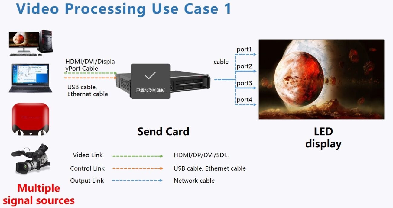
LED Display Topology Diagram
Table of Contents
ToggleCore Components
LED Lamp Beads: The Soul of Illumination
LED lamp beads are semiconductor components that emit light through PN junction electroluminescence. When current flows, holes in the P-region and electrons in the N-region recombine at the PN junction, releasing energy manifested as light. Combining RGB tri-color lamp beads allows for the display of various colors through different brightness ratios.
Main Types:
- Through-Hole Type: Used for outdoor large screens, featuring high brightness and strong weather resistance
- Surface-Mounted Device (SMD): Used for indoor fine-pitch displays, offering high pixel density and detailed imagery
- COB (Chip-On-Board): Multiple chips directly encapsulated, providing excellent heat dissipation and high reliability
Display Module: The Basic Display Unit
Multiple LED chips are arranged in a pattern to form a display module, which includes a driver circuit board, driver chips, and connecting wires. The driver chips determine the LED chips’ on/off status and brightness based on control signals.
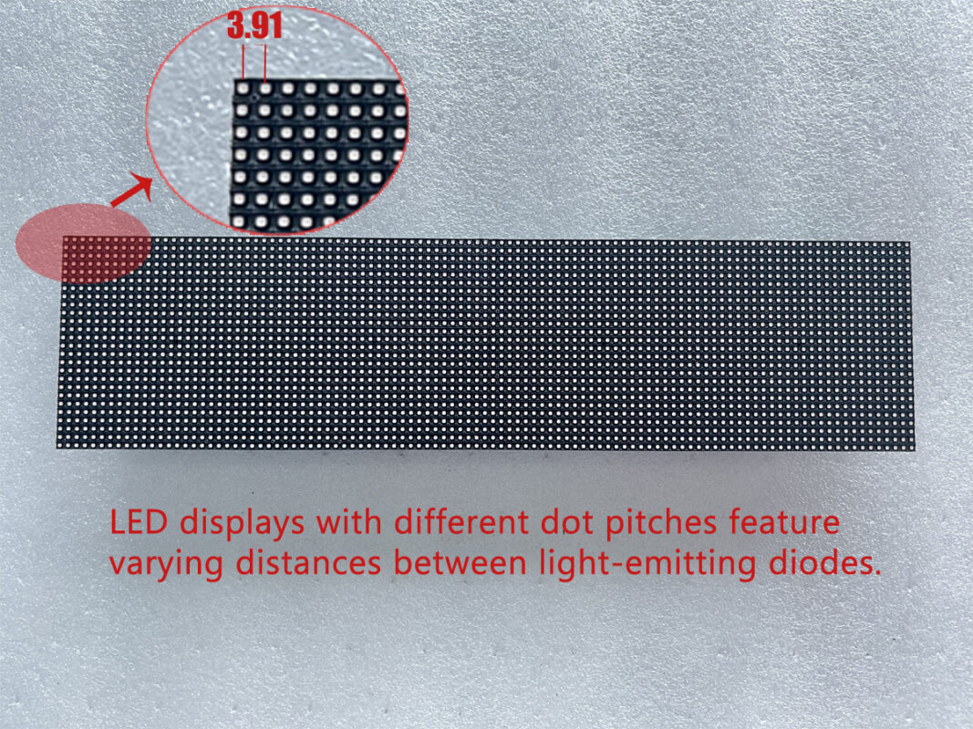
The dot pitch of an LED display primarily depends on the LED chips.
Control System: The brain of the display
- Transmitter Card: Converts external video signals into specialized digital signals for the display
- Receiver Card: Receives signals and distributes them to the driver chips of each display module
Power Supply System
The power distribution box converts external voltage to the required display voltage, equipped with overload, short-circuit, and leakage protection devices to ensure safety.
Core Display Principles
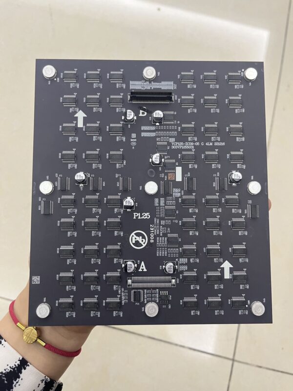
P1 COB Display Panel
Monochrome LED Screen
Current control activates or deactivates LEDs. The control system converts text/patterns into binary signals, and the driver chip energizes or de-energizes corresponding LEDs based on instructions.
Color LED Screen: RGB Primary Color Mixing
Each pixel comprises red, green, and blue LEDs. By adjusting the brightness ratio of these three colors, various hues are produced. For example, red and green together yield yellow, while all three colors fully lit produce white.
Gray Scale Control: Key to Image Detail
Utilizes Pulse Width Modulation (PWM) technology. The driver chip controls the LED’s power-on duration via high-frequency pulses to achieve different brightness levels. Mainstream displays feature 16-bit gray scale (65,536 levels), enabling smooth color transitions.
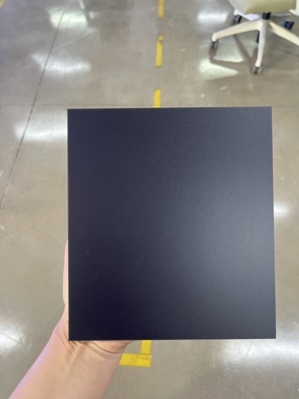
P1 COB Display Module
Signal Processing Flow
- Signal Input: Raw signals output from external devices (HDMI, VGA, SDI, etc.)
- Signal Conversion: The transmitter card converts signals into LED-specific formats, performing image scaling and color correction
- Signal Distribution: The receiver card distributes signals to individual module driver chips
- Drive Control: Driver chips employ constant-current drive technology to precisely control each LED
- Image Display: Thousands of LEDs illuminate according to their assigned brightness and color to form the image
Differences Between LED Display Types
Indoor Displays vs. Outdoor Displays
- Indoor Displays: Brightness 500-1500 cd/m², high pixel density (P1.2-P2.5), IP30-IP40 protection rating
- Outdoor Displays: Brightness 3000-8000 cd/m², low pixel density (P6-P10), ≥IP65 protection rating, equipped with auto-brightness adjustment and cooling systems
Small-Pitch Displays vs Standard Displays
- Small-Pitch Screens: Utilize constant-current drive + full-scan technology, with individual LED control for fine image detail; feature metal backplane + heat spreader cooling, high power consumption
- Conventional Screens: Employ scan drive (1/8 or 1/16 scan), lower cost, rely on natural convection cooling
Transparent LED Display
Features a transparent frame + perforated PCB structure with 70%-90% light transmittance. Supports irregular-shaped splicing, suitable for glass curtain walls and similar applications.
Common Fault Analysis
Localized Black Screen
- Causes: Power supply failure, signal cable contact issues, damaged driver chip, burned-out LED
- Solutions: Check power cable voltage, reseat signal cables, measure driver chip current, test individual LEDs
Bright/Dark Lines
- Cause: Driver chip short circuit (bright line) or open circuit (dark line), signal cable breakage
- Solution: Locate and replace faulty module’s driver chip, inspect signal cables
Screen Flickering
- Cause: Unstable power supply, signal interference, low refresh rate, improper driver parameter settings
- Solution: Stabilize power supply, eliminate signal interference, increase refresh rate to 60Hz+, adjust driver parameters
Color Deviation
- Cause: Poor LED consistency, incorrect color calibration parameters, uneven drive current
- Solution: Select LEDs from the same batch, recalibrate using a colorimeter, check drive current
Dead/Bad Pixels
- Cause: LED PN junction short circuit (bright spot) or open circuit (dark spot), poor solder joint
- Solution: Test individual LEDs, repair solder joints, replace driver chip
Entire Display Not Lighting
- Cause: Main power supply failure, control system malfunction, common line breakage
- Solution: Inspect main switch in distribution box, reseat transmitter card, check common lines
Maintenance Key Points
Core Component Maintenance
- Prevent LED overcurrent, maintain temperature ≤50°C
- Stabilize driver chip supply voltage, prevent electrostatic discharge
- Regularly monitor current, promptly replace abnormal chips
Operating Environment Control
- Indoor Displays: Maintain humidity 40%-60%, perform regular dust removal, avoid vibration
- Outdoor Displays: Quarterly inspection of waterproof seals, testing of lightning protection devices, ensuring proper heat dissipation
Operating Procedures
- Power-on sequence: Power distribution box → Control system → Display screen
- Power-off sequence: Display screen → Control system → Power distribution box
- Enable automatic brightness adjustment to avoid prolonged high-brightness operation
- Avoid displaying static images for extended periods; switch images hourly
Regular Maintenance Schedule
- Daily: Inspect display images and auxiliary equipment
- Weekly: Dust removal, wiring inspection
- Monthly: Test drive current, inspect waterproof seals
- Quarterly: Calibrate color brightness, test lightning protection devices
- Annually: Comprehensive control system inspection, replace aged wiring
Technological Trends
Mini/Micro LED
LED size reduced to under 0.1mm, achieving 10,000 PPI pixel density. Utilizes active driving with ≤1μs response time, suitable for high-end TVs and AR/VR devices.
Flexible LED Screens
Utilizing flexible substrates and packaging, these screens bend and fold with a weight only one-third that of traditional displays. Ideal for irregular building facades and wearable devices.
Green Energy-Saving Technology
High-efficiency LED chips boost electroluminescence efficiency to over 200 lm/W. Combined with AI algorithms for dynamic brightness adjustment, power consumption is reduced by over 30%.
Integrated Control
Single-chip control system integrates multiple functions, reducing signal latency to under 1ms. AI enables automatic fault detection, image optimization, and centralized cloud management.
Understanding LED display principles empowers you to avoid parameter-based misguidance during selection, perform precise troubleshooting during malfunctions, and execute scientifically efficient maintenance—truly grasping both the “what” and the “why.”

